US20180135456A1 - Modeling to detect gas turbine anomalies - Google Patents
Modeling to detect gas turbine anomalies Download PDFInfo
- Publication number
- US20180135456A1 US20180135456A1 US15/354,997 US201615354997A US2018135456A1 US 20180135456 A1 US20180135456 A1 US 20180135456A1 US 201615354997 A US201615354997 A US 201615354997A US 2018135456 A1 US2018135456 A1 US 2018135456A1
- Authority
- US
- United States
- Prior art keywords
- turbine system
- sensors
- audio output
- controller
- processors
- Prior art date
- Legal status (The legal status is an assumption and is not a legal conclusion. Google has not performed a legal analysis and makes no representation as to the accuracy of the status listed.)
- Abandoned
Links
- 230000015654 memory Effects 0.000 claims abstract description 22
- 238000002485 combustion reaction Methods 0.000 claims description 36
- 230000006399 behavior Effects 0.000 claims description 31
- 239000000446 fuel Substances 0.000 claims description 19
- 239000000523 sample Substances 0.000 claims description 9
- 230000003287 optical effect Effects 0.000 claims description 5
- 238000012545 processing Methods 0.000 claims description 4
- 230000003068 static effect Effects 0.000 claims description 4
- 239000007789 gas Substances 0.000 description 24
- 238000000034 method Methods 0.000 description 18
- 238000012800 visualization Methods 0.000 description 12
- 230000005236 sound signal Effects 0.000 description 6
- MWUXSHHQAYIFBG-UHFFFAOYSA-N nitrogen oxide Inorganic materials O=[N] MWUXSHHQAYIFBG-UHFFFAOYSA-N 0.000 description 5
- 238000010586 diagram Methods 0.000 description 4
- 238000009826 distribution Methods 0.000 description 4
- 238000004519 manufacturing process Methods 0.000 description 4
- 230000009471 action Effects 0.000 description 3
- 239000012530 fluid Substances 0.000 description 3
- 230000001788 irregular Effects 0.000 description 3
- 238000012423 maintenance Methods 0.000 description 3
- 238000012544 monitoring process Methods 0.000 description 3
- 230000003595 spectral effect Effects 0.000 description 3
- 230000008901 benefit Effects 0.000 description 2
- 239000006227 byproduct Substances 0.000 description 2
- 229910002090 carbon oxide Inorganic materials 0.000 description 2
- 239000000567 combustion gas Substances 0.000 description 2
- 238000004891 communication Methods 0.000 description 2
- 238000013461 design Methods 0.000 description 2
- 238000011161 development Methods 0.000 description 2
- VNWKTOKETHGBQD-UHFFFAOYSA-N methane Chemical compound C VNWKTOKETHGBQD-UHFFFAOYSA-N 0.000 description 2
- 230000002093 peripheral effect Effects 0.000 description 2
- 238000003860 storage Methods 0.000 description 2
- 229910052815 sulfur oxide Inorganic materials 0.000 description 2
- UGFAIRIUMAVXCW-UHFFFAOYSA-N Carbon monoxide Chemical class [O+]#[C-] UGFAIRIUMAVXCW-UHFFFAOYSA-N 0.000 description 1
- 230000005355 Hall effect Effects 0.000 description 1
- UFHFLCQGNIYNRP-UHFFFAOYSA-N Hydrogen Chemical compound [H][H] UFHFLCQGNIYNRP-UHFFFAOYSA-N 0.000 description 1
- 230000002159 abnormal effect Effects 0.000 description 1
- 230000005856 abnormality Effects 0.000 description 1
- 230000003321 amplification Effects 0.000 description 1
- 238000004458 analytical method Methods 0.000 description 1
- 230000002547 anomalous effect Effects 0.000 description 1
- 230000008859 change Effects 0.000 description 1
- 239000000498 cooling water Substances 0.000 description 1
- 230000001419 dependent effect Effects 0.000 description 1
- 238000001514 detection method Methods 0.000 description 1
- 230000000694 effects Effects 0.000 description 1
- 238000001914 filtration Methods 0.000 description 1
- 230000006870 function Effects 0.000 description 1
- 230000036541 health Effects 0.000 description 1
- 229930195733 hydrocarbon Natural products 0.000 description 1
- 150000002430 hydrocarbons Chemical class 0.000 description 1
- 239000001257 hydrogen Substances 0.000 description 1
- 229910052739 hydrogen Inorganic materials 0.000 description 1
- 238000009434 installation Methods 0.000 description 1
- 239000007788 liquid Substances 0.000 description 1
- 239000000463 material Substances 0.000 description 1
- 239000000203 mixture Substances 0.000 description 1
- 239000003345 natural gas Substances 0.000 description 1
- 238000003199 nucleic acid amplification method Methods 0.000 description 1
- 238000010248 power generation Methods 0.000 description 1
- 230000008569 process Effects 0.000 description 1
- 238000011084 recovery Methods 0.000 description 1
- XTQHKBHJIVJGKJ-UHFFFAOYSA-N sulfur monoxide Chemical class S=O XTQHKBHJIVJGKJ-UHFFFAOYSA-N 0.000 description 1
- 230000001960 triggered effect Effects 0.000 description 1
- 238000011144 upstream manufacturing Methods 0.000 description 1
- 230000000007 visual effect Effects 0.000 description 1
Images


Classifications
-
- G—PHYSICS
- G05—CONTROLLING; REGULATING
- G05B—CONTROL OR REGULATING SYSTEMS IN GENERAL; FUNCTIONAL ELEMENTS OF SUCH SYSTEMS; MONITORING OR TESTING ARRANGEMENTS FOR SUCH SYSTEMS OR ELEMENTS
- G05B23/00—Testing or monitoring of control systems or parts thereof
- G05B23/02—Electric testing or monitoring
- G05B23/0205—Electric testing or monitoring by means of a monitoring system capable of detecting and responding to faults
- G05B23/0208—Electric testing or monitoring by means of a monitoring system capable of detecting and responding to faults characterized by the configuration of the monitoring system
- G05B23/0216—Human interface functionality, e.g. monitoring system providing help to the user in the selection of tests or in its configuration
-
- F—MECHANICAL ENGINEERING; LIGHTING; HEATING; WEAPONS; BLASTING
- F02—COMBUSTION ENGINES; HOT-GAS OR COMBUSTION-PRODUCT ENGINE PLANTS
- F02C—GAS-TURBINE PLANTS; AIR INTAKES FOR JET-PROPULSION PLANTS; CONTROLLING FUEL SUPPLY IN AIR-BREATHING JET-PROPULSION PLANTS
- F02C9/00—Controlling gas-turbine plants; Controlling fuel supply in air- breathing jet-propulsion plants
-
- F—MECHANICAL ENGINEERING; LIGHTING; HEATING; WEAPONS; BLASTING
- F01—MACHINES OR ENGINES IN GENERAL; ENGINE PLANTS IN GENERAL; STEAM ENGINES
- F01D—NON-POSITIVE DISPLACEMENT MACHINES OR ENGINES, e.g. STEAM TURBINES
- F01D21/00—Shutting-down of machines or engines, e.g. in emergency; Regulating, controlling, or safety means not otherwise provided for
- F01D21/003—Arrangements for testing or measuring
-
- G—PHYSICS
- G06—COMPUTING; CALCULATING OR COUNTING
- G06F—ELECTRIC DIGITAL DATA PROCESSING
- G06F30/00—Computer-aided design [CAD]
-
- F—MECHANICAL ENGINEERING; LIGHTING; HEATING; WEAPONS; BLASTING
- F05—INDEXING SCHEMES RELATING TO ENGINES OR PUMPS IN VARIOUS SUBCLASSES OF CLASSES F01-F04
- F05D—INDEXING SCHEME FOR ASPECTS RELATING TO NON-POSITIVE-DISPLACEMENT MACHINES OR ENGINES, GAS-TURBINES OR JET-PROPULSION PLANTS
- F05D2220/00—Application
- F05D2220/30—Application in turbines
- F05D2220/32—Application in turbines in gas turbines
Definitions
- the subject matter disclosed herein relates to turbomachinery, and more specifically, to modeling to detect gas turbine anomalies, events, or problems using generated audio output.
- Plant operators may be removed from the physical noises of the equipment (e.g., gas turbines) in plants as the equipment is running. For example, the operator may be monitoring the operation of the plant at a location remote from the plant, sound-proofing of the equipment operating in the plants may reduce the audible noise emitted, or the like. As such, the operators oftentimes rely on alarms created by a control system to protect the equipment. However, operators may become desensitized to or ignore the alarms for significant periods of time, which may lead to an undesirable operating condition of the equipment occurring. In addition, there may be certain locations of the equipment where including sensors is not feasible (e.g., physically, logistically, thermally, etc.). Nevertheless, operators may find it desirable to learn about behavior characteristics at those locations when determining whether an anomaly, event, or problem is present.
- the equipment e.g., gas turbines
- a turbine system includes a number of sensors, each sensor disposed in a respective location of the turbine system and generating a respective signal, a controller capable of generating a controller output, the controller output being at least partially derived from the respective signal from the number of sensors, and an electronic device including memories storing processor-executable routines, and one or more processors configured to access and execute the one or more routines encoded by the one or more memories wherein the one or more routines, when executed, cause the one or more processors to receive one or more inputs, the inputs being at least one of the respective signals from one of the number of sensors, the controller output, or some combination thereof, and generate an audio output using one or more models that incorporate the one or more inputs.
- a device includes one or more memories storing one or more processor-executable routines, and one or more processors configured to access and execute the one or more routines encoded by the one or more memories wherein the one or more routines, when executed, cause the one or more processors to receive one or more inputs, the inputs being at least one of a respective signal from a number of sensors of a turbine system, an output of a controller of the turbine system, or some combination thereof, and generate an audio output using one or more models that incorporate the one or more inputs.
- one or more tangible, non-transitory computer-readable mediums includes instructions that, when executed by one or more processors, cause the one or more processors to receive one or more inputs, the inputs beings at least one of a respective signal from a number of sensors, a controller output, or some combination thereof, wherein each sensor of the number of sensors are disposed at a respective location of a turbine system, and generate an audio output using one or more models that incorporate the one or more inputs.
- FIG. 1 is a block diagram of a turbine system that enables modeling to detect anomalies, events, or problems via generated audio output using one or more sensors, in accordance with an embodiment
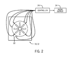
- FIG. 2 is a schematic diagram of example locations of the turbine system where the sensors may be located, in accordance with an embodiment
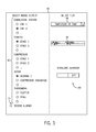
- FIG. 3 is a screenshot of a graphical user interface for utilization in listening to generated audio output from the turbine system, in accordance with an embodiment
- FIG. 4 is a flow chart illustrating an embodiment of a method for modeling to detect anomalies, events, or problems via generated audio output, in accordance with an embodiment.
- embodiments of the present disclosure generally relate to a system and method for detecting modeled gas turbine anomalies, events, or problems using generated audio output. That is, some embodiments enable gas turbine operators to monitor modeled behavior to detect anomalies, events, or problems via generated audible noise using data obtained from sensors included in or attached to the turbine system and/or output from a controller.
- the model may receive inputs from various available instrumentation (e.g., sensors) and control parameters to simulate behavior of desired locations or phenomenon.
- the sensors may be disposed in or on various locations of the turbine system, such as the compressor, intake (e.g., inlet), turbine, and the like.
- the sensor signals may be output from thermocouples and/or dynamic pressure transmitters in various locations of the turbine system (e.g., sensors near the intake and representing valve stroke of the gas entering the intake and the amount open of inlet guide vanes (IGV) and inlet bleed heat (IBH), sensor at fuel intake of combustion system, pressure sensors at the intake, pressure sensors at compressor discharge, thermocouples at compressor discharge, thermocouples at turbine exhaust, and so forth).
- IGV inlet guide vanes
- IBH inlet bleed heat
- data from the sensors included in or on the turbine system and/or output from a controller may be used to model behavior (e.g., pressure dynamics, thermal dynamics, fluid dynamics, etc.) and generate audio representing that behavior in the locations without sensors to enable detecting anomalies, events, or problems in the locations without sensors.
- the data from the sensors may be obtained during any period of operation (e.g., startup, full operation, and/or shutdown) of the turbine system.
- the sensors may include dynamic pressure sensors, thermocouple sensors, and/or other sensors that are already present in the gas turbine. Leveraging the existing sensors may reduce new instrumentation and installation costs. Additionally, the sensors may include clearance probes, optical probes, microphones, accelerometers or strain gages, dynamic pressure sensors, and the like. The sensors may be located in any feasible location on the gas turbine or within the gas turbine, such as in an inlet, compressor, turbine, holes of a casing of the turbine system, borescope ports, fuel intake, or the like. In some embodiments, the sensors may emit signals to a controller and/or computing device executing a software application.
- the software application may cause a processor to model behavior within certain locations in the gas turbine, generate audio signals representing the behavior, and output the audio signals via audio output devices of the controller and/or computing device.
- the plant operators may listen to the audio output generated using modeled behavior and detect anomalies, events, or problems based on a change in the sound of the turbine system, rather than solely relying on controller alarms.
- the anomalies, events, or problems that are modeled may include flutter, rotating stall, whistling caused by resonance of the compressor bleed cavities and/or various cavities or wheel spaces in the turbine, items (e.g., bolts, debris, etc.) left inside the turbine system when the system is operational, compressor surge, and the like.
- FIG. 1 illustrates a block diagram of a turbine system 10 that enables modeling to detect anomalies, events, or problems via generated audio output, in accordance with an embodiment of the present disclosure.
- the turbine system 10 includes a turbine engine 12 and an aftertreatment system 14 .
- the aftertreatment system 14 is included optionally and the turbine system 10 may include some other system (e.g., heat recovery steam generator) instead of the aftertreatment system 14 or another system in addition to the aftertreatment system 14 .
- the turbine system 10 does not include the aftertreatment system 14 .
- the turbine system 10 may be a power generation system.
- the turbine system 10 may use liquid or gas fuel, such as natural gas and/or a hydrogen-rich synthetic gas, to run the turbine system 10 .
- the turbine system 10 includes an air intake section 16 , a compressor 18 , a combustion system 20 , and the turbine 12 .
- the turbine 12 may be drivingly coupled to the compressor 18 via a shaft.
- air enters the turbine system 10 through the air intake section 16 (indicated by the arrows 17 ) and is pressurized in the compressor 18 .
- the intake section 16 may include an inlet.
- the compressor 18 may include a number of compressor blades coupled to the shaft. The rotation of the shaft causes rotation of the compressor blades, thereby drawing air into the compressor 18 and compressing the air prior to entry into the combustion system 20 .
- the compressed air 17 may be mixed with fuel 19 for combustion within one or more combustion cans 23 .
- the combustion cans 23 may include one or more fuel nozzles that may inject a fuel-air mixture into the combustion cans 23 in a suitable ratio for optimal combustion, emissions, fuel consumption, power output, and so forth.
- the combustion of the air 17 and fuel 19 generates hot pressurized exhaust gases, which may then be utilized to drive one or more turbine blades within the turbine 12 .
- the combustion gases flowing into and through the turbine 12 flow against and between the turbine blades, thereby driving the turbine blades and, thus, the shaft into rotation to drive a load 21 , such as an electrical generator in a power plant.
- the rotation of the shaft also causes blades within the compressor 18 to draw in and pressurize the air received by the intake 16 .
- the combustion gases that flow through the turbine 12 may exit the downstream end 15 of the turbine 12 as a stream of exhaust gas.
- the exhaust gas stream may continue to flow in the downstream direction towards the aftertreatment system 14 .
- the downstream end 15 may be fluidly coupled to the aftertreatment system 14 .
- the exhaust gas may include certain byproducts, such as nitrogen oxides (NO x ), sulfur oxides (SO x ), carbon oxides (CO x ), and unburned hydrocarbons. Due to certain regulations, the aftertreatment system 14 may be employed to reduce or substantially minimize the concentration of such byproducts prior to releasing the exhaust gas stream into the atmosphere.
- One or more sensors 22 may be included in the combustion system 20 , the compressor 18 , the turbine 12 , various holes in a casing of the turbine system 10 , borescope ports, inlets of the intake section 16 , or any feasible location of the turbine system 10 .
- the sensors 22 may include any type of dynamic pressure sensors, accelerometers, strain gages, or the like.
- the sensors 22 may be bearing seismic sensors (e.g., accelerometers) or rotor proximity probes that are configured to listen to rotor dynamics to enable detecting tonal or discrete frequency.
- the sensors 22 may be located over a particular blade stage in the compressor 18 and/or the turbine 12 .
- the sensors 22 may be dynamic pressure sensors that are located in a flow path, or the sensors 22 may be accelerometers located on the casing of the compressor 18 and/or the turbine 12 .
- the sensors 22 may already be included in the assembled combustion system 20 and no other instrumentation may be added to the combustion system 20 to perform certain embodiments of the present disclosure.
- the sensors 22 may be configured to sense pressure signals or waves in any desirable amplitude and frequency range within the compressor 18 , the combustion system 20 , and/or the turbine 12 . Further, in some embodiments, the sensors 22 may be configured to sense thermal characteristics in or near the intake 16 , the compressor 18 , the combustion system 20 , and/or the turbine 12 .
- the sensors 22 may include piezoelectric materials that generate electric signals resulting from pressure.
- the sensors 22 may include Micro-Electrico-Mechanical Systems (MEMs) sensors, Hall effect sensors, magnetorestrictive sensors, or any other sensor designed to sense vibration, pressure, or the like.
- the sensors 22 may include optical sensors that are configured to measure combustion dynamics optically.
- the sensors 22 may include thermocouples configured to sense temperature.
- the sensors 22 may include communication circuitry that enables the sensors 22 to be communicatively coupled to a controller 24 and/or a computing device 25 via a wireless (e.g., Bluetooth® Low Energy, ZigBee®, WiFi®) or wired connection (e.g., Ethernet).
- the computing device 25 may include a laptop, a smartphone, a tablet, a personal computer, a human-machine interface, or the like.
- the computing device 25 may be coupled to the controller 24 and/or the sensors 22 , but the computing device 25 may not be configured to control the turbine system 10 . That is, the computing device 25 may receive the same inputs as the controller 24 but does not provide the same outputs (e.g., control commands) to the turbine system 10 .
- a distributed control system is enabled where the computing device 25 functions as a monitoring tool to enable providing feedback to operators, and the controller 24 controls the turbine system 10 .
- computationally expensive and demanding modeling may be delegated to the computing device 25 , which may include one or more processors with enhanced performance as compared to any processor of the controller 24 , as described below.
- the computing device 25 may be configured to control the turbine system 10 , as well as provide feedback to operators.
- the sensors 22 may include a microphone or array of microphones included in the gas turbine system 10 and/or disposed external to the gas turbine system 10 .
- the microphones or array of microphones may be disposed within or near the inlet, the exhaust stack, the combustion system 20 , the compressor 18 , the turbine 12 , or the like.
- the microphone or array of microphones may send detected sound to the controller 24 for use in a sound level meter or series of sound level meters. In some embodiments the detected sound may be indicative of combustion dynamics.
- the sensors 22 may transmit signals indicative of pressure (e.g., static, dynamic), vibration, and/or thermal characteristics to the controller 24 and/or the computing device 25 .
- the sensors 22 may transmit signals during any stage of operation (e.g., startup, combustion at full speed operation, shutdown) of the turbine system 10 .
- the sensors 22 may be active and transmit signals of any detected noise even when the turbine system 10 is shutdown.
- the controller 24 and/or the computing device 25 may receive the signals from the sensors 22 and model (e.g., mathematical, physics-based) behavior (e.g., pressure dynamics, thermal dynamics, fluid dynamics, etc.) in desired locations of the turbine system 10 based on the signals.
- the model may simulate any dynamic pressure changes in the desired locations that is indicative of an anomaly, event, or problem.
- the model may utilize one or more inputs (e.g., operational parameters) derived from the sensor signals. More specifically, the model may receive inputs from the sensors 22 related to amount of fuel entering the combustion system 20 , the air entering the intake 16 , pressure at the intake 16 , pressure at compressor discharge, temperature at compressor discharge, and/or temperature in the exhaust, among others.
- the model when the modeling is performed by the computing device 25 , the model may receive an input related to control parameters (e.g., outputs for fuel flow, air flow, etc.) from the controller 24 to use when modeling the behavior and generating the audio output.
- control parameters e.g., outputs for fuel flow, air flow, etc.
- the locations where the behavior is modeled may not include the sensors 22 due to certain constraints (e.g., physical, thermal, logistic, etc.) of those locations.
- the controller 24 and/or the computing device 25 may generate audio signals suitable for outputting (e.g., via an audio output device associated with the computing device 25 and the controller 24 ).
- compressor maps may be used that may include high order equation fittings.
- the model may use the higher order model and/or equation fitting of the compressor maps as inputs to model the anomalies, events, or problems in certain locations without sensors 22 .
- the compressor maps may be used by the model to model the pressure downstream of the compressor 18 , the pressure at compressor discharge, or the like and audio signals may be generated that represent the pressure to enable detection of anomalies, events, or problems.
- the controller 24 and/or the computing device 25 may each include one or more tangible, non-transitory computer-readable mediums (e.g., memories 26 and 27 ) storing computer instructions that, when executed by a respective processor 28 and 29 of the controller 24 and/or the computing device 25 , cause the processor 28 and 29 to receive the sensor signals and/or controller outputs (e.g., control parameters being at least partially derived from the signals from the sensors 22 ), generate audio signals using one or more models based on the sensor signals and/or controller outputs, and output the generated audio signals via a respective audio output device 30 and 31 (e.g., speaker, bullhorn, megaphone, siren, headphone, amplifier, public address (PA) system, etc.).
- a respective audio output device 30 and 31 e.g., speaker, bullhorn, megaphone, siren, headphone, amplifier, public address (PA) system, etc.
- controller 24 and/or the computing device 25 may include communication circuitry, such as a network interface, that is configured to receive the sensor signals and/or controller outputs and transmit the sensor signals and/or controller outputs to the processors 28 and/or 29 .
- the processors 28 and 29 may be any type of computer processor or microprocessor capable of executing computer-executable code. Moreover, the processors 28 and 29 may include multiple processors or microprocessors, one or more “general-purpose” processors or microprocessors, one or more special-purpose processors or microprocessors, and/or one or more application specific integrated circuits (ASICS), or some combination thereof. For example, the processors 28 and 29 may include one or more reduced instruction set (RISC) processors. In some embodiments, the processor 29 of the computing device 25 may be more powerful than the processor 28 of the controller 24 in terms of performance (e.g., processing speed).
- RISC reduced instruction set
- the memories 26 and 27 may be any suitable articles of manufacture that can serve as media to store processor-executable routines, code, data, or the like. These articles of manufacture may represent computer-readable media (e.g., any suitable form of memory or storage) that may store the processor-executable code or routines used by the respective processors 28 and 29 to perform the presently disclosed techniques.
- the memories 26 and 27 may include volatile memory (e.g., a random access memory (RAM)), nonvolatile memory (e.g., a read-only memory (ROM)), flash memory, a hard drive, or any other suitable optical, magnetic, or solid-state storage medium, or a combination thereof.
- RAM random access memory
- ROM read-only memory
- flash memory e.g., a hard drive, or any other suitable optical, magnetic, or solid-state storage medium, or a combination thereof.
- the memories 26 and 27 may also be used to store any data (e.g., recordings of the generated audio output for a desired amount of time), analysis of the data
- the processors 28 and 29 may execute software applications that include a graphical user interface (GUI) that enables a user to select model outputs of the turbine system 10 for which to generate the audio output.
- GUI graphical user interface
- the GUI may enable the user to select model output by phenomenon, component, location in the turbine, as well as parameter to be modelled (e.g., vibration, pressure, etc.). Additional features relating to the GUI are discussed below.
- the operator may listen to the generated audio representing, for example, pressure or dynamics in the turbine system 10 at a location remote from the actual turbine system 10 using the controller 24 and/or the computing device 25 .
- the operator may be in relatively close proximity to the turbine system 10 while listening to the audio output via the controller 24 and/or the computing device 25 .
- the sensors 22 may include one or more processors (e.g., controllers) capable of performing the modeling described above internally.
- the sensors 22 may also include one or more memories storing instructions for the modeling that are accessible and executable by the one or more sensor processors.
- the sensors 22 e.g., Profibus, Fieldbus, Modbus, etc.
- the controller 24 may communicate the control parameters (e.g., fuel flow, air flow, etc.) to the sensors to use in the modeling, as well.
- the sensors 22 may independently model the behavior of certain locations of the turbine system 10 without processing help from the computing device 25 or the controller 24 .
- the modeled behavior may be used to generate the audio output by the sensor processors or the modeled behavior may be sent to the computing device 25 and/or the controller 24 to generate the audio output.
- the operator may determine that there is an anomaly, event, or problem occurring in the gas turbine system 10 . Indeed, the user may pinpoint which area of the turbine system 10 (e.g., combustion can 23 , compressor 18 , turbine 12 , inlet, etc.) is experiencing the anomaly, event, or problem by using the disclosed techniques. For example, the operator may discern that the current noise emitted from the compressor 18 during a stage of operation sounds different (e.g., abnormal) than the noise emitted from the compressor 18 during that stage of operation when the compressor 18 is operating as expected. As such, the operator may perform a preventative action, such as shut down the turbine system 10 , check the compressor 18 , perform maintenance on the compressor 18 , perform replacement of components in the compressor 18 , schedule maintenance and/or replacement, or the like.
- a preventative action such as shut down the turbine system 10 , check the compressor 18 , perform maintenance on the compressor 18 , perform replacement of components in the compressor 18 , schedule maintenance and/or replacement, or the like.
- FIG. 2 is a schematic diagram of example locations of the turbine system 10 where the sensors 22 may be located, in accordance with an embodiment.
- the locations where the sensors 22 may be located include at least the compressor 18 (e.g., intake, stage by stage, and discharge), the turbine 12 (e.g., intake, stage by stage, and exhaust), combustion cans of the combustion system 20 , the intake 16 , various holes of a casing of the turbine system 10 , fuel intake of the combustion system 20 , a borescope port, and the like.
- sensors 22 there are various locations of the turbine system 10 where it is not feasible (e.g., physically, thermally, logistically, etc.) to include sensors 22 and some embodiments of the present disclosure include modeling behavior in those locations using data from the sensors 22 in other locations and/or outputs from the controller 24 .
- a combination of sensors 22 e.g., different axial or circumferential locations, monitoring different components of the turbine system 10 ) may be used to determine where anomalous behavior is originating.
- the sensors 22 may be accelerometers, dynamic pressure sensors (e.g., probes), strain gages, thermocouples, optical probes, or the like. Further, the sensors 22 may be located circumferentially around the turbine 12 and/or the compressor 18 .
- a respective sensor 22 may be coupled to at least each blade stage of the turbine 12 and/or the compressor 18 .
- six sensors 22 may be used (e.g., one sensor 22 located proximate each blade stage). It should be noted that, in some embodiments, there may not be a one-to-one relationship between the number of sensors 22 and the number of blade stages.
- one sensor 22 may be used to monitor all of the blade stages, a few sensors 22 may be used to monitor all of the blade stages, or more than one sensor 22 may be used to monitor a blade stage (e.g., circumferentially).
- the sensors 22 may be probes that are partially inserted into the turbine 12 , the compressor 18 , the combustion cans of the combustion system 20 , holes of a casing, borescope port, fuel intake of the combustion system 20 , and/or the intake 16 .
- the signals emitted by the sensors 22 may be sent to the controller 24 and/or the computing device 25 .
- the controller 24 and/or the computing device 25 may include a software application that generates audio output representative of anomalies, events, or problems using one or more models based on the signals and/or controller outputs and emits the audio output 34 .
- the software application may be downloadable from an application distribution platform installed on the controller 24 and/or the computing device 25 .
- the application distribution platform may be proprietary and private. Thus, in some embodiments, downloading of the software application that enables listening to the audio representative of the modeled pressure or vibration of the turbine system 10 during operation or while the turbine system 10 is shutdown may be restricted to authorized users. In this way, the application distribution platform may perform authentication of the controller 24 and/or the computing device 25 that requests to download the software application.
- the application distribution platform may be connected to a cloud-based computing system that maintains the software application, as well as other software applications and data. Also, the software application may be connected to the cloud-based computing system and may send data and receive data from the cloud-based computing system.
- FIG. 3 is a screenshot of a graphical user interface (GUI) 40 that displays a list 42 of model outputs available for which to generate audio output and receives a user selection of the model output, in accordance with an embodiment.
- GUI graphical user interface
- the model outputs are for locations and phenomena (e.g., flutter, stall, compressor surge, etc.) in the turbine system 10 in the depicted list 42
- the list 42 may include other model output selections, such as by component, parameter (e.g., vibration, pressure, etc.), and the like.
- the list 42 may include options for “high-impact items”, “high-risk items”, and/or “sort by event”. Sort by event may refer to fuel transfers, loading, peak, or the like.
- the GUI 40 displays an input selector 44 related to whether the user desires to receive control alarms related to the turbine system 10 .
- the list 42 includes radio button selectors for “CAN 1,” “CAN 2,” . . . of the combustion system 20 , “STAGE 1,” “STAGE 2,” . . . of the turbine 12 , “STAGE 1,” “STAGE 2,” . . . of the compressor 18 , “BEARING 1,” and “COMPRESSOR DISCHARGE,” . . . of the rotor, and “FLUTTER,” and “STALL,” . . . of phenomena.
- any number of locations and/or phenomena may be selectable through the GUI 40 .
- radio button selector may be included for each component of the turbine system 10 .
- a “select all” radio button selector may be included under each heading for the combustion system 20 , the turbine 12 , the compressor 18 , the rotor, phenomena, and so forth.
- the processor 28 and/or 29 may use one or more inputs from the available sensors (e.g., compressor discharge pressure, compressor discharge temperature, etc.) and/or controller outputs (e.g., fuel flow, air flow, etc.) to model behavior in the selected locations and/or phenomena and generate audio output representing the modeled behavior.
- sensors e.g., compressor discharge pressure, compressor discharge temperature, etc.
- controller outputs e.g., fuel flow, air flow, etc.
- the GUI 40 may display the list 42 as including model output selected to be listened to. It should be appreciated that there is a distinction between the model output selected to be generated and the model output selected to be listened to. For example, in some embodiments, the user may select to generate numerous model outputs at once and listen to them one at a time. Additionally or alternatively, in some embodiments, it may be desirable to listen to more than one generated output at a time.
- radio button selectors are used in the list 42 , it should be noted that any selection input element may be used such as a dropdown list, a checkbox, an input textbox, or the like. Additionally, in some embodiments, voice commands may be used to select the model outputs to listen to from the list 42 .
- the controller 24 and/or the computing device 25 may include a microphone that is configured to receive sounds and the processor 28 and 29 may be configured to process the sounds in order to select the desired model outputs to use when generating audio output using the one or more models.
- the user may use an input peripheral such as a mouse to move an arrow or hand selection icon around the GUI 40 .
- an input peripheral such as a mouse to move an arrow or hand selection icon around the GUI 40 .
- the radio button selector may toggle to a selected state if in a deselected state or may toggle to a deselected state if already in a selected state.
- the input peripheral may include a touchscreen. When the user touches a portion of the touchscreen where a radio button selector is located, the radio button selector may toggle to a selected state if in a deselected state or may toggle to a deselected state if already in a selected state.
- the model output locations in the combustion system 20 , the turbine 12 , the compressor 18 , and/or the rotor may be represented graphically, similar to FIG. 2 , on the GUI 40 .
- the user may select a graphical representation of the model output location on a visualization of the turbine system 10 to use to generate audio using the one or more models.
- the user may select the model output location from the list 42 and the graphical representation of the combustion system 20 , the turbine 12 , the compressor 18 , and/or the rotor may be highlighted in the turbine system 10 displayed on the GUI 40 depending on the selection. Further, the locations of sensors 22 that are used in the modeling at the selected location may be highlighted to provide an indication of which sensor signals were used as input to the model.
- the GUI 40 may display a visualization 46 of a sound wave representative of the generated audio emitted.
- a respective visualization 46 may include a respective sound wave for the respective locations that are selected.
- one or more visualizations 46 may include numerous sound waves to be overlaid. That is, one visualization 46 may include depictions of multiple sound waves to enable the user to compare the sound waves relative to one another more clearly.
- the information displayed on the visualization 46 may be performed independently of the audio output 34 .
- the audio output 34 may emit noises representing modeled pressure downstream of the compressor 18
- the visualization 46 displays sound waves overlaid for the modeled pressure downstream of the compressor 18 and combustion.
- the visualization 46 depicted is a time domain output (amplitude versus time), it should be appreciated that the visualization 46 may be a spectral output (frequency versus amplitude).
- a spectral output may enable a user to identify the frequency associated with any abnormality detected and may guide an action to be taken.
- the GUI 40 may provide an option to select/deselect the plots to be displayed.
- a graphical selector element such as dropdown list 48 , may be used to enable the user to select whether to display the time domain outputs, spectral outputs, or both.
- the software application associated with the GUI 40 may output a live feed of the generated audio associated with the selected model output location to the respective audio output device 30 and/or 31 of the controller 24 and/or the computing device 25 .
- the user may listen to the generated audio associated with the selected model output location and/or view the sound wave associated with the audio of the selected model output location.
- Using both the audio output 34 and the visual representation 46 in conjunction may enable the user to double check a determination of whether a modeled behavior indicates an anomaly, event, or problem is present.
- the sound wave visualization 46 may be used to confirm that a loud or unexpected noise was modeled based on data from the associated sensors 22 and/or the controller outputs during operation of the turbine system 10 and the noise was not due to some event near the operator using the computing device 25 . That is, the generated audio output 34 and the sound wave visualization 46 may be used as a check on each other.
- the GUI 40 may also include a modeling behavior input selector 49 , which enables the operator to turn on or off modeling behavior in desired locations of the turbine system 10 .
- the modeling behavior input selector 49 may include a sliding bar input selector.
- any suitable input selector may be used such as radio buttons or the like.
- the user may select the model output(s) for which to generate audio using one or more models based on signals from associated sensors and/or controller outputs. For example, the user may select just one model output location, one model output phenomena, may select just a particular component (e.g., one or more stages of the compressor 18 , the turbine 12 , etc.), or may select all of the model output locations at once. In this way, the user may detect whether an anomaly, event, or problem is present in the turbine system 10 in general or on an individual component basis by listening to generated audio output 34 representing the modeled behavior (e.g., pressure, vibration, thermal) within or near (e.g., downstream, upstream) specific components during operation.
- the modeled behavior e.g., pressure, vibration, thermal
- the sensors 22 may emit signals during full-speed operation of the turbine system 10 , any other stage of operation, or even when the turbine system 10 is shutdown.
- the generated audio output 34 may be provided in real-time or near real-time as operation (e.g., combustion) is occurring due to the simulated real-time feedback provided by the one or more models.
- the generated audio output 34 may be provided via the controller 24 and/or the computing device 25 , which may be physically located away from the actual turbine system 10 (e.g., in a control room or in a separate building).
- the GUI 40 may provide an input selection to the operator to select whether to receive control alarms.
- Receiving information e.g., type of alarm, status, parameters, timestamp
- certain control alarms may relate to vibration above a threshold, oil pressure below a threshold, oil pressure above a threshold, bearing temperature above a threshold, cooling water failure, power failure, or the like.
- the user may view the control alarm that is currently activated and listen to the audio output 34 generated using one or more models based on inputs from one or more of the sensors 22 and/or the controller 24 to determine that the irregular audio output 34 is caused by the event indicated by the control alarm. Likewise, when the user hears irregular, generated audio output 34 during operation and the control alarms are not triggered or activated, then the user may determine that the control alarms should be recalibrated or checked to make sure they are operating properly, the sensors 22 should be recalibrated or checked, the one or more models should be adjusted or checked, or the like.
- FIG. 4 is a flow chart illustrating an embodiment of a method 50 for modeling to detect anomalies, events, or problems via generated audio output, in accordance with an embodiment.
- the method 50 may be performed by other processors disposed on other devices that may be capable of communicating with the sensors 22 , such as the processor 28 of the controller 24 , processors of the sensors 22 , or other components associated with the turbine system 10 .
- the following method 50 describes a number of operations that may be performed, it should be noted that the method 50 may be performed in a variety of suitable orders and all of the operations may not be performed.
- the method 50 may be wholly executed by the computing device 25 or the execution may be distributed between the computing device 25 and the controller 24 . Further, the method 50 may be implemented as computer instructions included in a software application stored on the memory 26 or 27 . As previously discussed, the software application may be obtainable from a software distribution platform.
- the processor 29 may receive (block 52 ) an input selection of the model output location(s) for which to generate audio output 34 .
- the input selection may be of model output phenomenon, component of the turbine system 10 , parameter (e.g., vibration, pressure, etc.), or the like.
- the input selection may be entered by a user using the GUI 40 described above. For example, the user may select the model output location from the list 42 . The user may select a subset of the model output locations (one or more but not all), or all of the model output locations.
- the processor 29 may cause a network interface to tune-in to the sensors 22 associated with the selected model output location (e.g., compressor 18 , intake 16 , turbine 12 , combustion can 23 , holes 34 , fuel intake, borescope port 36 , etc.). Additionally or alternatively, the network interface may already be communicatively coupled to the sensors 22 associated with the selected model output location.
- the selected model output location e.g., compressor 18 , intake 16 , turbine 12 , combustion can 23 , holes 34 , fuel intake, borescope port 36 , etc.
- the network interface may already be communicatively coupled to the sensors 22 associated with the selected model output location.
- the processor 29 may receive (block 54 ) signals (e.g., inputs) from the sensors 22 associated with the selected model output location(s) and/or controller outputs (e.g., fuel flow, air flow, etc.).
- signals e.g., inputs
- controller outputs e.g., fuel flow, air flow, etc.
- each sensor 22 may include a dynamic pressure sensor, probe, gage, accelerometer, thermocouple, or the like that senses pressure waves, vibration waves, or thermal characteristics in the particular location and emits the appropriate signals.
- the processor 29 may generate (block 56 ) audio output 34 using one or more models based on the sensor signals and/or the controller outputs.
- a first model may use physics-based equations that model behavior (e.g., pressure dynamics, fluid dynamics, thermal dynamics, etc.) in the turbine system 10 based on the sensor signals and/or the controller outputs.
- various operational parameters e.g., derived from sensor signals
- may be used as inputs to the first model may include amount of fuel intake, amount of air entering the intake 16 , pressure at the intake 16 , pressure at compressor discharge, temperature at compressor discharge, and/or temperature in the exhaust from the turbine 12 .
- a second model (e.g., compressor map) may be used that includes higher order equation fitting that provides input related to compressor discharge pressure to the first model.
- the first and second models may be combined into one model.
- the processor 29 may generate the audio output 34 representing the modeled behavior.
- the processor 29 may perform additional processing or calculations on the audio output 34 .
- the processor 29 may perform A-weighting, B-weighting, C-weighting, D-weighting, reverse A-weighting, reverse B-weighting, reverse C-weighting, reverse D-weighting, or the like. It should be appreciated that any type of suitable frequency-dependent amplification or filtering may be performed by the processor 29 .
- the processor 29 may output (block 58 ) the generated audio output 34 via the audio output device 30 or 31 .
- the user may listen to the audio output 34 (based on the modeled behavior) to detect whether there is an anomaly, event, or problem present in or near the selected model output location(s) or the turbine system 10 in general. That is, an irregular noise generated and emitted during operation may be indicative of an issue with or near the selected model output location or with the turbine system 10 as a whole. Anomalies that may be detected may include flutter, rotating stall, whistling caused by resonance of the compressor bleed cavities and/or various cavities or wheel spaces in the turbine 12 , compressor surge, and/or loose items (e.g., bolts, debris) inside of components of the turbine system 10 .
- the method 50 may be repeated, as shown by arrow 58 , and the user may select the next model output location for which to generate audio output.
- the method 50 may be repeated until the user listens to generated audio for all of the model output locations in the turbine system 10 or until the operator identifies a modeled behavior that represents an anomaly, event, or problem in the turbine system 10 and performs a preventative action, as described above.
- the user may select a combination of the model output locations for which to generate audio output.
- the generated audio output 34 may be generated using one or more models based on data obtained via one or more sensors 22 in any feasible location of the turbine system 10 and/or controller output.
- the sensors 22 may already be installed in the turbine system 10 , and thus, no additional instrumentation is installed to perform the disclosed techniques.
- the sensors 22 may sense pressure (static or dynamic) or vibration waves and/or temperature. Further, the sensors 22 may emit the signals to the controller 24 and/or the computing device 25 , which may execute a software application to generate audio output 34 using the one or more models based on the sensor signals and/or controller outputs and to emit via the audio output devices 30 and 31 .
- some embodiments enable the user to select the model output by phenomenon, component, location in the turbine system 10 , and/or parameter (e.g., vibration, pressure, etc.) for which to generate audio output.
Landscapes
- Engineering & Computer Science (AREA)
- Physics & Mathematics (AREA)
- General Engineering & Computer Science (AREA)
- General Physics & Mathematics (AREA)
- Mechanical Engineering (AREA)
- Chemical & Material Sciences (AREA)
- Theoretical Computer Science (AREA)
- Combustion & Propulsion (AREA)
- Human Computer Interaction (AREA)
- Automation & Control Theory (AREA)
- Geometry (AREA)
- Evolutionary Computation (AREA)
- Computer Hardware Design (AREA)
- Testing And Monitoring For Control Systems (AREA)
- Control Of Positive-Displacement Air Blowers (AREA)
Abstract
Description
- The subject matter disclosed herein relates to turbomachinery, and more specifically, to modeling to detect gas turbine anomalies, events, or problems using generated audio output.
- Plant operators may be removed from the physical noises of the equipment (e.g., gas turbines) in plants as the equipment is running. For example, the operator may be monitoring the operation of the plant at a location remote from the plant, sound-proofing of the equipment operating in the plants may reduce the audible noise emitted, or the like. As such, the operators oftentimes rely on alarms created by a control system to protect the equipment. However, operators may become desensitized to or ignore the alarms for significant periods of time, which may lead to an undesirable operating condition of the equipment occurring. In addition, there may be certain locations of the equipment where including sensors is not feasible (e.g., physically, logistically, thermally, etc.). Nevertheless, operators may find it desirable to learn about behavior characteristics at those locations when determining whether an anomaly, event, or problem is present.
- Certain embodiments commensurate in scope with the originally claimed subject matter are summarized below. These embodiments are not intended to limit the scope of the claimed subject matter, but rather these embodiments are intended only to provide a brief summary of possible forms of the subject matter. Indeed, the subject matter may encompass a variety of forms that may be similar to or different from the embodiments set forth below.
- In one embodiment, a turbine system includes a number of sensors, each sensor disposed in a respective location of the turbine system and generating a respective signal, a controller capable of generating a controller output, the controller output being at least partially derived from the respective signal from the number of sensors, and an electronic device including memories storing processor-executable routines, and one or more processors configured to access and execute the one or more routines encoded by the one or more memories wherein the one or more routines, when executed, cause the one or more processors to receive one or more inputs, the inputs being at least one of the respective signals from one of the number of sensors, the controller output, or some combination thereof, and generate an audio output using one or more models that incorporate the one or more inputs.
- In one embodiment, a device includes one or more memories storing one or more processor-executable routines, and one or more processors configured to access and execute the one or more routines encoded by the one or more memories wherein the one or more routines, when executed, cause the one or more processors to receive one or more inputs, the inputs being at least one of a respective signal from a number of sensors of a turbine system, an output of a controller of the turbine system, or some combination thereof, and generate an audio output using one or more models that incorporate the one or more inputs.
- In one embodiment, one or more tangible, non-transitory computer-readable mediums includes instructions that, when executed by one or more processors, cause the one or more processors to receive one or more inputs, the inputs beings at least one of a respective signal from a number of sensors, a controller output, or some combination thereof, wherein each sensor of the number of sensors are disposed at a respective location of a turbine system, and generate an audio output using one or more models that incorporate the one or more inputs.
- These and other features, aspects, and advantages of the present subject matter will become better understood when the following detailed description is read with reference to the accompanying drawings in which like characters represent like parts throughout the drawings, wherein:
-
FIG. 1 is a block diagram of a turbine system that enables modeling to detect anomalies, events, or problems via generated audio output using one or more sensors, in accordance with an embodiment; -
FIG. 2 is a schematic diagram of example locations of the turbine system where the sensors may be located, in accordance with an embodiment; -
FIG. 3 is a screenshot of a graphical user interface for utilization in listening to generated audio output from the turbine system, in accordance with an embodiment; and -
FIG. 4 is a flow chart illustrating an embodiment of a method for modeling to detect anomalies, events, or problems via generated audio output, in accordance with an embodiment. - One or more specific embodiments of the present subject matter will be described below. In an effort to provide a concise description of these embodiments, all features of an actual implementation may not be described in the specification. It should be appreciated that in the development of any such actual implementation, as in any engineering or design project, numerous implementation-specific decisions must be made to achieve the developers' specific goals, such as compliance with system-related and business-related constraints, which may vary from one implementation to another. Moreover, it should be appreciated that such a development effort might be complex and time consuming, but would nevertheless be a routine undertaking of design, fabrication, and manufacture for those of ordinary skill having the benefit of this disclosure.
- When introducing elements of various embodiments of the present subject matter, the articles “a,” “an,” “the,” and “said” are intended to mean that there are one or more of the elements. The terms “comprising,” “including,” and “having” are intended to be inclusive and mean that there may be additional elements other than the listed elements.
- As previously discussed, plant operators may ignore or become desensitized to certain alarms related to gas turbine health that are emitted at control stations remote from the gas turbine. As such, gas turbine equipment issues may arise at the plants that result in significant equipment downtime (e.g., the equipment is not operational) or maintenance costs. Further, it may not be feasible (e.g., physically, logistically, thermally, etc.) to install sensors in certain locations of the gas turbine equipment. Thus, it is now generally recognized that improved techniques for detecting gas turbine anomalies, events, or problems are desirable.
- Accordingly, embodiments of the present disclosure generally relate to a system and method for detecting modeled gas turbine anomalies, events, or problems using generated audio output. That is, some embodiments enable gas turbine operators to monitor modeled behavior to detect anomalies, events, or problems via generated audible noise using data obtained from sensors included in or attached to the turbine system and/or output from a controller. For example, the model may receive inputs from various available instrumentation (e.g., sensors) and control parameters to simulate behavior of desired locations or phenomenon. The sensors may be disposed in or on various locations of the turbine system, such as the compressor, intake (e.g., inlet), turbine, and the like. For example, the sensor signals may be output from thermocouples and/or dynamic pressure transmitters in various locations of the turbine system (e.g., sensors near the intake and representing valve stroke of the gas entering the intake and the amount open of inlet guide vanes (IGV) and inlet bleed heat (IBH), sensor at fuel intake of combustion system, pressure sensors at the intake, pressure sensors at compressor discharge, thermocouples at compressor discharge, thermocouples at turbine exhaust, and so forth). As may be appreciated, it may not be feasible to dispose sensors in or on certain portions of the
turbine system 10 due to various constraints (e.g., physical, thermal, etc.). Thus, in some embodiments, data from the sensors included in or on the turbine system and/or output from a controller may be used to model behavior (e.g., pressure dynamics, thermal dynamics, fluid dynamics, etc.) and generate audio representing that behavior in the locations without sensors to enable detecting anomalies, events, or problems in the locations without sensors. In some embodiments, the data from the sensors may be obtained during any period of operation (e.g., startup, full operation, and/or shutdown) of the turbine system. - As described below, the sensors may include dynamic pressure sensors, thermocouple sensors, and/or other sensors that are already present in the gas turbine. Leveraging the existing sensors may reduce new instrumentation and installation costs. Additionally, the sensors may include clearance probes, optical probes, microphones, accelerometers or strain gages, dynamic pressure sensors, and the like. The sensors may be located in any feasible location on the gas turbine or within the gas turbine, such as in an inlet, compressor, turbine, holes of a casing of the turbine system, borescope ports, fuel intake, or the like. In some embodiments, the sensors may emit signals to a controller and/or computing device executing a software application. The software application may cause a processor to model behavior within certain locations in the gas turbine, generate audio signals representing the behavior, and output the audio signals via audio output devices of the controller and/or computing device. The plant operators may listen to the audio output generated using modeled behavior and detect anomalies, events, or problems based on a change in the sound of the turbine system, rather than solely relying on controller alarms. The anomalies, events, or problems that are modeled may include flutter, rotating stall, whistling caused by resonance of the compressor bleed cavities and/or various cavities or wheel spaces in the turbine, items (e.g., bolts, debris, etc.) left inside the turbine system when the system is operational, compressor surge, and the like.
- Turning now to the drawings,
FIG. 1 illustrates a block diagram of aturbine system 10 that enables modeling to detect anomalies, events, or problems via generated audio output, in accordance with an embodiment of the present disclosure. In some embodiments, theturbine system 10 includes aturbine engine 12 and anaftertreatment system 14. It should be noted that theaftertreatment system 14 is included optionally and theturbine system 10 may include some other system (e.g., heat recovery steam generator) instead of theaftertreatment system 14 or another system in addition to theaftertreatment system 14. In some embodiments, theturbine system 10 does not include theaftertreatment system 14. In certain embodiments, theturbine system 10 may be a power generation system. Theturbine system 10 may use liquid or gas fuel, such as natural gas and/or a hydrogen-rich synthetic gas, to run theturbine system 10. As shown, theturbine system 10 includes anair intake section 16, acompressor 18, acombustion system 20, and theturbine 12. Theturbine 12 may be drivingly coupled to thecompressor 18 via a shaft. In operation, air enters theturbine system 10 through the air intake section 16 (indicated by the arrows 17) and is pressurized in thecompressor 18. Theintake section 16 may include an inlet. Thecompressor 18 may include a number of compressor blades coupled to the shaft. The rotation of the shaft causes rotation of the compressor blades, thereby drawing air into thecompressor 18 and compressing the air prior to entry into thecombustion system 20. - As compressed air exits the
compressor 18 and enters thecombustion system 20, thecompressed air 17 may be mixed withfuel 19 for combustion within one ormore combustion cans 23. For example, thecombustion cans 23 may include one or more fuel nozzles that may inject a fuel-air mixture into thecombustion cans 23 in a suitable ratio for optimal combustion, emissions, fuel consumption, power output, and so forth. The combustion of theair 17 andfuel 19 generates hot pressurized exhaust gases, which may then be utilized to drive one or more turbine blades within theturbine 12. In operation, the combustion gases flowing into and through theturbine 12 flow against and between the turbine blades, thereby driving the turbine blades and, thus, the shaft into rotation to drive aload 21, such as an electrical generator in a power plant. As discussed above, the rotation of the shaft also causes blades within thecompressor 18 to draw in and pressurize the air received by theintake 16. - The combustion gases that flow through the
turbine 12 may exit thedownstream end 15 of theturbine 12 as a stream of exhaust gas. The exhaust gas stream may continue to flow in the downstream direction towards theaftertreatment system 14. For instance, thedownstream end 15 may be fluidly coupled to theaftertreatment system 14. As a result of the combustion process, the exhaust gas may include certain byproducts, such as nitrogen oxides (NOx), sulfur oxides (SOx), carbon oxides (COx), and unburned hydrocarbons. Due to certain regulations, theaftertreatment system 14 may be employed to reduce or substantially minimize the concentration of such byproducts prior to releasing the exhaust gas stream into the atmosphere. - One or
more sensors 22 may be included in thecombustion system 20, thecompressor 18, theturbine 12, various holes in a casing of theturbine system 10, borescope ports, inlets of theintake section 16, or any feasible location of theturbine system 10. In some embodiments, thesensors 22 may include any type of dynamic pressure sensors, accelerometers, strain gages, or the like. For example, thesensors 22 may be bearing seismic sensors (e.g., accelerometers) or rotor proximity probes that are configured to listen to rotor dynamics to enable detecting tonal or discrete frequency. In some embodiments, thesensors 22 may be located over a particular blade stage in thecompressor 18 and/or theturbine 12. For example, thesensors 22 may be dynamic pressure sensors that are located in a flow path, or thesensors 22 may be accelerometers located on the casing of thecompressor 18 and/or theturbine 12. In some embodiments, thesensors 22 may already be included in the assembledcombustion system 20 and no other instrumentation may be added to thecombustion system 20 to perform certain embodiments of the present disclosure. In some embodiments, thesensors 22 may be configured to sense pressure signals or waves in any desirable amplitude and frequency range within thecompressor 18, thecombustion system 20, and/or theturbine 12. Further, in some embodiments, thesensors 22 may be configured to sense thermal characteristics in or near theintake 16, thecompressor 18, thecombustion system 20, and/or theturbine 12. - The
sensors 22 may include piezoelectric materials that generate electric signals resulting from pressure. In some embodiments, thesensors 22 may include Micro-Electrico-Mechanical Systems (MEMs) sensors, Hall effect sensors, magnetorestrictive sensors, or any other sensor designed to sense vibration, pressure, or the like. Additionally, thesensors 22 may include optical sensors that are configured to measure combustion dynamics optically. Also, thesensors 22 may include thermocouples configured to sense temperature. Thesensors 22 may include communication circuitry that enables thesensors 22 to be communicatively coupled to acontroller 24 and/or acomputing device 25 via a wireless (e.g., Bluetooth® Low Energy, ZigBee®, WiFi®) or wired connection (e.g., Ethernet). In some embodiments, thecomputing device 25 may include a laptop, a smartphone, a tablet, a personal computer, a human-machine interface, or the like. - In some embodiments, the
computing device 25 may be coupled to thecontroller 24 and/or thesensors 22, but thecomputing device 25 may not be configured to control theturbine system 10. That is, thecomputing device 25 may receive the same inputs as thecontroller 24 but does not provide the same outputs (e.g., control commands) to theturbine system 10. In such an embodiment, a distributed control system is enabled where thecomputing device 25 functions as a monitoring tool to enable providing feedback to operators, and thecontroller 24 controls theturbine system 10. In some embodiments, computationally expensive and demanding modeling may be delegated to thecomputing device 25, which may include one or more processors with enhanced performance as compared to any processor of thecontroller 24, as described below. It should be noted that, in some embodiments, thecomputing device 25 may be configured to control theturbine system 10, as well as provide feedback to operators. - In some embodiments, the
sensors 22 may include a microphone or array of microphones included in thegas turbine system 10 and/or disposed external to thegas turbine system 10. For example, the microphones or array of microphones may be disposed within or near the inlet, the exhaust stack, thecombustion system 20, thecompressor 18, theturbine 12, or the like. In some embodiments, the microphone or array of microphones may send detected sound to thecontroller 24 for use in a sound level meter or series of sound level meters. In some embodiments the detected sound may be indicative of combustion dynamics. - During operation, the
sensors 22 may transmit signals indicative of pressure (e.g., static, dynamic), vibration, and/or thermal characteristics to thecontroller 24 and/or thecomputing device 25. Thesensors 22 may transmit signals during any stage of operation (e.g., startup, combustion at full speed operation, shutdown) of theturbine system 10. In some embodiments, thesensors 22 may be active and transmit signals of any detected noise even when theturbine system 10 is shutdown. Thecontroller 24 and/or thecomputing device 25 may receive the signals from thesensors 22 and model (e.g., mathematical, physics-based) behavior (e.g., pressure dynamics, thermal dynamics, fluid dynamics, etc.) in desired locations of theturbine system 10 based on the signals. For example, the model may simulate any dynamic pressure changes in the desired locations that is indicative of an anomaly, event, or problem. The model may utilize one or more inputs (e.g., operational parameters) derived from the sensor signals. More specifically, the model may receive inputs from thesensors 22 related to amount of fuel entering thecombustion system 20, the air entering theintake 16, pressure at theintake 16, pressure at compressor discharge, temperature at compressor discharge, and/or temperature in the exhaust, among others. In addition, in some embodiments, when the modeling is performed by thecomputing device 25, the model may receive an input related to control parameters (e.g., outputs for fuel flow, air flow, etc.) from thecontroller 24 to use when modeling the behavior and generating the audio output. - It should be noted that the locations where the behavior is modeled may not include the
sensors 22 due to certain constraints (e.g., physical, thermal, logistic, etc.) of those locations. Further, based on the modeled behavior, thecontroller 24 and/or thecomputing device 25 may generate audio signals suitable for outputting (e.g., via an audio output device associated with thecomputing device 25 and the controller 24). In addition, in some embodiments, compressor maps may be used that may include high order equation fittings. The model may use the higher order model and/or equation fitting of the compressor maps as inputs to model the anomalies, events, or problems in certain locations withoutsensors 22. For example, the compressor maps may be used by the model to model the pressure downstream of thecompressor 18, the pressure at compressor discharge, or the like and audio signals may be generated that represent the pressure to enable detection of anomalies, events, or problems. - The
controller 24 and/or thecomputing device 25 may each include one or more tangible, non-transitory computer-readable mediums (e.g.,memories 26 and 27) storing computer instructions that, when executed by arespective processor controller 24 and/or thecomputing device 25, cause theprocessor audio output device 30 and 31 (e.g., speaker, bullhorn, megaphone, siren, headphone, amplifier, public address (PA) system, etc.). It should be noted that non-transitory merely indicates that the media is tangible and not a signal. Further, thecontroller 24 and/or thecomputing device 25 may include communication circuitry, such as a network interface, that is configured to receive the sensor signals and/or controller outputs and transmit the sensor signals and/or controller outputs to theprocessors 28 and/or 29. - The
processors processors processors processor 29 of thecomputing device 25 may be more powerful than theprocessor 28 of thecontroller 24 in terms of performance (e.g., processing speed). - The
memories respective processors memories memories - Generally, the
processors turbine system 10 for which to generate the audio output. In some embodiments, the GUI may enable the user to select model output by phenomenon, component, location in the turbine, as well as parameter to be modelled (e.g., vibration, pressure, etc.). Additional features relating to the GUI are discussed below. As may be appreciated, the operator may listen to the generated audio representing, for example, pressure or dynamics in theturbine system 10 at a location remote from theactual turbine system 10 using thecontroller 24 and/or thecomputing device 25. In some embodiments, the operator may be in relatively close proximity to theturbine system 10 while listening to the audio output via thecontroller 24 and/or thecomputing device 25. - In some embodiments, the
sensors 22 may include one or more processors (e.g., controllers) capable of performing the modeling described above internally. Thesensors 22 may also include one or more memories storing instructions for the modeling that are accessible and executable by the one or more sensor processors. In some embodiments, the sensors 22 (e.g., Profibus, Fieldbus, Modbus, etc.) may be communicatively coupled to each other to form a discrete loop and/or network. In this way, thesensors 22 may communicate the respective data obtained to each other to enable the modeling. In some embodiments, thecontroller 24 may communicate the control parameters (e.g., fuel flow, air flow, etc.) to the sensors to use in the modeling, as well. Thesensors 22 may independently model the behavior of certain locations of theturbine system 10 without processing help from thecomputing device 25 or thecontroller 24. The modeled behavior may be used to generate the audio output by the sensor processors or the modeled behavior may be sent to thecomputing device 25 and/or thecontroller 24 to generate the audio output. - Based on the generated audio output that is output via the
audio output devices 30 and/or 31, the operator may determine that there is an anomaly, event, or problem occurring in thegas turbine system 10. Indeed, the user may pinpoint which area of the turbine system 10 (e.g., combustion can 23,compressor 18,turbine 12, inlet, etc.) is experiencing the anomaly, event, or problem by using the disclosed techniques. For example, the operator may discern that the current noise emitted from thecompressor 18 during a stage of operation sounds different (e.g., abnormal) than the noise emitted from thecompressor 18 during that stage of operation when thecompressor 18 is operating as expected. As such, the operator may perform a preventative action, such as shut down theturbine system 10, check thecompressor 18, perform maintenance on thecompressor 18, perform replacement of components in thecompressor 18, schedule maintenance and/or replacement, or the like. -
FIG. 2 is a schematic diagram of example locations of theturbine system 10 where thesensors 22 may be located, in accordance with an embodiment. The locations where thesensors 22 may be located include at least the compressor 18 (e.g., intake, stage by stage, and discharge), the turbine 12 (e.g., intake, stage by stage, and exhaust), combustion cans of thecombustion system 20, theintake 16, various holes of a casing of theturbine system 10, fuel intake of thecombustion system 20, a borescope port, and the like. It should be noted that there are various locations of theturbine system 10 where it is not feasible (e.g., physically, thermally, logistically, etc.) to includesensors 22 and some embodiments of the present disclosure include modeling behavior in those locations using data from thesensors 22 in other locations and/or outputs from thecontroller 24. Thus, it should also be noted that in some embodiments, a combination of sensors 22 (e.g., different axial or circumferential locations, monitoring different components of the turbine system 10) may be used to determine where anomalous behavior is originating. As depicted, thesensors 22 may be accelerometers, dynamic pressure sensors (e.g., probes), strain gages, thermocouples, optical probes, or the like. Further, thesensors 22 may be located circumferentially around theturbine 12 and/or thecompressor 18. - Although the signals from the
sensors 22 are shown as sent to thecontroller 24, it should be noted that the signals may also be sent to thecomputing device 25, which may perform similar functionality related to generating audio output using one or more models based on the signals and/or control parameters and outputting the audio as thecontroller 24. As depicted, in some embodiments, arespective sensor 22 may be coupled to at least each blade stage of theturbine 12 and/or thecompressor 18. Thus, if there are six blade stages in thecompressor 18, then sixsensors 22 may be used (e.g., onesensor 22 located proximate each blade stage). It should be noted that, in some embodiments, there may not be a one-to-one relationship between the number ofsensors 22 and the number of blade stages. For example, onesensor 22 may be used to monitor all of the blade stages, afew sensors 22 may be used to monitor all of the blade stages, or more than onesensor 22 may be used to monitor a blade stage (e.g., circumferentially). Likewise, there may benumerous sensors 22 used to monitor the inlet or just asingle sensor 22 may monitor the inlet. - In some embodiments, the
sensors 22 may be probes that are partially inserted into theturbine 12, thecompressor 18, the combustion cans of thecombustion system 20, holes of a casing, borescope port, fuel intake of thecombustion system 20, and/or theintake 16. The signals emitted by thesensors 22 may be sent to thecontroller 24 and/or thecomputing device 25. Thecontroller 24 and/or thecomputing device 25 may include a software application that generates audio output representative of anomalies, events, or problems using one or more models based on the signals and/or controller outputs and emits theaudio output 34. - It should be noted that the software application may be downloadable from an application distribution platform installed on the
controller 24 and/or thecomputing device 25. The application distribution platform may be proprietary and private. Thus, in some embodiments, downloading of the software application that enables listening to the audio representative of the modeled pressure or vibration of theturbine system 10 during operation or while theturbine system 10 is shutdown may be restricted to authorized users. In this way, the application distribution platform may perform authentication of thecontroller 24 and/or thecomputing device 25 that requests to download the software application. The application distribution platform may be connected to a cloud-based computing system that maintains the software application, as well as other software applications and data. Also, the software application may be connected to the cloud-based computing system and may send data and receive data from the cloud-based computing system. -
FIG. 3 is a screenshot of a graphical user interface (GUI) 40 that displays alist 42 of model outputs available for which to generate audio output and receives a user selection of the model output, in accordance with an embodiment. Although the model outputs are for locations and phenomena (e.g., flutter, stall, compressor surge, etc.) in theturbine system 10 in the depictedlist 42, it should be noted that thelist 42 may include other model output selections, such as by component, parameter (e.g., vibration, pressure, etc.), and the like. In some embodiments, thelist 42 may include options for “high-impact items”, “high-risk items”, and/or “sort by event”. Sort by event may refer to fuel transfers, loading, peak, or the like. Additionally, theGUI 40 displays aninput selector 44 related to whether the user desires to receive control alarms related to theturbine system 10. As depicted, thelist 42 includes radio button selectors for “CAN 1,” “CAN 2,” . . . of thecombustion system 20, “STAGE 1,” “STAGE 2,” . . . of theturbine 12, “STAGE 1,” “STAGE 2,” . . . of thecompressor 18, “BEARING 1,” and “COMPRESSOR DISCHARGE,” . . . of the rotor, and “FLUTTER,” and “STALL,” . . . of phenomena. Thus, as may be appreciated, any number of locations and/or phenomena may be selectable through theGUI 40. For example, as depicted, “CAN 2,” “STAGE 1,” and “Bearing 1” are selected. Although just one radio button is displayed for a particular blade stage of theturbine 12 and thecompressor 18, it should be noted that additional radio buttons may be displayed as selectable to the user. It should be noted that a “select all” radio button selector may be included for each component of theturbine system 10. For example, a “select all” radio button selector may be included under each heading for thecombustion system 20, theturbine 12, thecompressor 18, the rotor, phenomena, and so forth. When the user selects the model output locations and/or phenomena from thelist 42, theprocessor 28 and/or 29 may use one or more inputs from the available sensors (e.g., compressor discharge pressure, compressor discharge temperature, etc.) and/or controller outputs (e.g., fuel flow, air flow, etc.) to model behavior in the selected locations and/or phenomena and generate audio output representing the modeled behavior. - In addition, the
GUI 40 may display thelist 42 as including model output selected to be listened to. It should be appreciated that there is a distinction between the model output selected to be generated and the model output selected to be listened to. For example, in some embodiments, the user may select to generate numerous model outputs at once and listen to them one at a time. Additionally or alternatively, in some embodiments, it may be desirable to listen to more than one generated output at a time. - Further, although radio button selectors are used in the
list 42, it should be noted that any selection input element may be used such as a dropdown list, a checkbox, an input textbox, or the like. Additionally, in some embodiments, voice commands may be used to select the model outputs to listen to from thelist 42. Thus, thecontroller 24 and/or thecomputing device 25 may include a microphone that is configured to receive sounds and theprocessor - The user may use an input peripheral such as a mouse to move an arrow or hand selection icon around the
GUI 40. When the user depresses and releases a button on the mouse and the selection icon is above a radio button selector, the radio button selector may toggle to a selected state if in a deselected state or may toggle to a deselected state if already in a selected state. Additionally, the input peripheral may include a touchscreen. When the user touches a portion of the touchscreen where a radio button selector is located, the radio button selector may toggle to a selected state if in a deselected state or may toggle to a deselected state if already in a selected state. - In some embodiments, the model output locations in the
combustion system 20, theturbine 12, thecompressor 18, and/or the rotor may be represented graphically, similar toFIG. 2 , on theGUI 40. In this way, instead of, or in addition, to selecting the model output locations from thelist 42, the user may select a graphical representation of the model output location on a visualization of theturbine system 10 to use to generate audio using the one or more models. Additionally, the user may select the model output location from thelist 42 and the graphical representation of thecombustion system 20, theturbine 12, thecompressor 18, and/or the rotor may be highlighted in theturbine system 10 displayed on theGUI 40 depending on the selection. Further, the locations ofsensors 22 that are used in the modeling at the selected location may be highlighted to provide an indication of which sensor signals were used as input to the model. - When the user selects a particular model output location, the
GUI 40 may display avisualization 46 of a sound wave representative of the generated audio emitted. Thus, the user may be able to visualize the sound wave on theGUI 40 via thevisualization 46 that is being displayed by a display of thecontroller 24 and/or thecomputing device 25. In some embodiments, arespective visualization 46 may include a respective sound wave for the respective locations that are selected. Additionally or alternatively, one ormore visualizations 46 may include numerous sound waves to be overlaid. That is, onevisualization 46 may include depictions of multiple sound waves to enable the user to compare the sound waves relative to one another more clearly. It should be noted that the information displayed on thevisualization 46 may be performed independently of theaudio output 34. For example, theaudio output 34 may emit noises representing modeled pressure downstream of thecompressor 18, while thevisualization 46 displays sound waves overlaid for the modeled pressure downstream of thecompressor 18 and combustion. - Although the embodiment of the
visualization 46 depicted is a time domain output (amplitude versus time), it should be appreciated that thevisualization 46 may be a spectral output (frequency versus amplitude). A spectral output may enable a user to identify the frequency associated with any abnormality detected and may guide an action to be taken. Further, in some embodiments, theGUI 40 may provide an option to select/deselect the plots to be displayed. For example, a graphical selector element, such asdropdown list 48, may be used to enable the user to select whether to display the time domain outputs, spectral outputs, or both. - Further, the software application associated with the
GUI 40 may output a live feed of the generated audio associated with the selected model output location to the respectiveaudio output device 30 and/or 31 of thecontroller 24 and/or thecomputing device 25. Thus, in some embodiments the user may listen to the generated audio associated with the selected model output location and/or view the sound wave associated with the audio of the selected model output location. Using both theaudio output 34 and thevisual representation 46 in conjunction may enable the user to double check a determination of whether a modeled behavior indicates an anomaly, event, or problem is present. For example, thesound wave visualization 46 may be used to confirm that a loud or unexpected noise was modeled based on data from the associatedsensors 22 and/or the controller outputs during operation of theturbine system 10 and the noise was not due to some event near the operator using thecomputing device 25. That is, the generatedaudio output 34 and thesound wave visualization 46 may be used as a check on each other. - In some embodiments, the
GUI 40 may also include a modelingbehavior input selector 49, which enables the operator to turn on or off modeling behavior in desired locations of theturbine system 10. As depicted, the modelingbehavior input selector 49 may include a sliding bar input selector. However, it should be understood that any suitable input selector may be used such as radio buttons or the like. - Using the
list 42 on theGUI 40, the user may select the model output(s) for which to generate audio using one or more models based on signals from associated sensors and/or controller outputs. For example, the user may select just one model output location, one model output phenomena, may select just a particular component (e.g., one or more stages of thecompressor 18, theturbine 12, etc.), or may select all of the model output locations at once. In this way, the user may detect whether an anomaly, event, or problem is present in theturbine system 10 in general or on an individual component basis by listening to generatedaudio output 34 representing the modeled behavior (e.g., pressure, vibration, thermal) within or near (e.g., downstream, upstream) specific components during operation. As previously noted, thesensors 22 may emit signals during full-speed operation of theturbine system 10, any other stage of operation, or even when theturbine system 10 is shutdown. The generatedaudio output 34 may be provided in real-time or near real-time as operation (e.g., combustion) is occurring due to the simulated real-time feedback provided by the one or more models. Also, the generatedaudio output 34 may be provided via thecontroller 24 and/or thecomputing device 25, which may be physically located away from the actual turbine system 10 (e.g., in a control room or in a separate building). - Further, using the
input selector 44 for control alarms, theGUI 40 may provide an input selection to the operator to select whether to receive control alarms. Receiving information (e.g., type of alarm, status, parameters, timestamp) related to control alarms may be used in conjunction with the generatedaudio output 34 during operation of theturbine system 10 to perform diagnostics. For example, certain control alarms may relate to vibration above a threshold, oil pressure below a threshold, oil pressure above a threshold, bearing temperature above a threshold, cooling water failure, power failure, or the like. The user may view the control alarm that is currently activated and listen to theaudio output 34 generated using one or more models based on inputs from one or more of thesensors 22 and/or thecontroller 24 to determine that theirregular audio output 34 is caused by the event indicated by the control alarm. Likewise, when the user hears irregular, generatedaudio output 34 during operation and the control alarms are not triggered or activated, then the user may determine that the control alarms should be recalibrated or checked to make sure they are operating properly, thesensors 22 should be recalibrated or checked, the one or more models should be adjusted or checked, or the like. -
FIG. 4 is a flow chart illustrating an embodiment of amethod 50 for modeling to detect anomalies, events, or problems via generated audio output, in accordance with an embodiment. Although the following description of themethod 50 is described with reference to theprocessor 29 of thecomputing device 25, it should be noted that themethod 50 may be performed by other processors disposed on other devices that may be capable of communicating with thesensors 22, such as theprocessor 28 of thecontroller 24, processors of thesensors 22, or other components associated with theturbine system 10. Additionally, although the followingmethod 50 describes a number of operations that may be performed, it should be noted that themethod 50 may be performed in a variety of suitable orders and all of the operations may not be performed. It should be appreciated that themethod 50 may be wholly executed by thecomputing device 25 or the execution may be distributed between thecomputing device 25 and thecontroller 24. Further, themethod 50 may be implemented as computer instructions included in a software application stored on thememory - Referring now to the
method 50, theprocessor 29 may receive (block 52) an input selection of the model output location(s) for which to generateaudio output 34. It should be understood that in some embodiments, instead of location, the input selection may be of model output phenomenon, component of theturbine system 10, parameter (e.g., vibration, pressure, etc.), or the like. The input selection may be entered by a user using theGUI 40 described above. For example, the user may select the model output location from thelist 42. The user may select a subset of the model output locations (one or more but not all), or all of the model output locations. Based on the input selection, theprocessor 29 may cause a network interface to tune-in to thesensors 22 associated with the selected model output location (e.g.,compressor 18,intake 16,turbine 12, combustion can 23, holes 34, fuel intake, borescope port 36, etc.). Additionally or alternatively, the network interface may already be communicatively coupled to thesensors 22 associated with the selected model output location. - The
processor 29 may receive (block 54) signals (e.g., inputs) from thesensors 22 associated with the selected model output location(s) and/or controller outputs (e.g., fuel flow, air flow, etc.). As previously described, eachsensor 22 may include a dynamic pressure sensor, probe, gage, accelerometer, thermocouple, or the like that senses pressure waves, vibration waves, or thermal characteristics in the particular location and emits the appropriate signals. - Once the signals (e.g., inputs) are received, the
processor 29 may generate (block 56)audio output 34 using one or more models based on the sensor signals and/or the controller outputs. As previously discussed, a first model may use physics-based equations that model behavior (e.g., pressure dynamics, fluid dynamics, thermal dynamics, etc.) in theturbine system 10 based on the sensor signals and/or the controller outputs. For example, various operational parameters (e.g., derived from sensor signals) may be used as inputs to the first model may include amount of fuel intake, amount of air entering theintake 16, pressure at theintake 16, pressure at compressor discharge, temperature at compressor discharge, and/or temperature in the exhaust from theturbine 12. In some embodiments, a second model (e.g., compressor map) may be used that includes higher order equation fitting that provides input related to compressor discharge pressure to the first model. In some embodiments, the first and second models may be combined into one model. Theprocessor 29 may generate theaudio output 34 representing the modeled behavior. In some embodiments, theprocessor 29 may perform additional processing or calculations on theaudio output 34. For example, theprocessor 29 may perform A-weighting, B-weighting, C-weighting, D-weighting, reverse A-weighting, reverse B-weighting, reverse C-weighting, reverse D-weighting, or the like. It should be appreciated that any type of suitable frequency-dependent amplification or filtering may be performed by theprocessor 29. - The
processor 29 may output (block 58) the generatedaudio output 34 via theaudio output device turbine system 10 in general. That is, an irregular noise generated and emitted during operation may be indicative of an issue with or near the selected model output location or with theturbine system 10 as a whole. Anomalies that may be detected may include flutter, rotating stall, whistling caused by resonance of the compressor bleed cavities and/or various cavities or wheel spaces in theturbine 12, compressor surge, and/or loose items (e.g., bolts, debris) inside of components of theturbine system 10. - If the user selected to listen to the audio generated for a single model output location and determines that the generated
audio output 34 is satisfactory (e.g., regular noise during operation), then themethod 50 may be repeated, as shown byarrow 58, and the user may select the next model output location for which to generate audio output. Themethod 50 may be repeated until the user listens to generated audio for all of the model output locations in theturbine system 10 or until the operator identifies a modeled behavior that represents an anomaly, event, or problem in theturbine system 10 and performs a preventative action, as described above. In some embodiments, the user may select a combination of the model output locations for which to generate audio output. - Technical effects of the subject matter include modeling to detect an anomaly, event, or problem in a
turbine system 10 using generated audio output. The generatedaudio output 34 may be generated using one or more models based on data obtained via one ormore sensors 22 in any feasible location of theturbine system 10 and/or controller output. In some embodiments, thesensors 22 may already be installed in theturbine system 10, and thus, no additional instrumentation is installed to perform the disclosed techniques. Thesensors 22 may sense pressure (static or dynamic) or vibration waves and/or temperature. Further, thesensors 22 may emit the signals to thecontroller 24 and/or thecomputing device 25, which may execute a software application to generateaudio output 34 using the one or more models based on the sensor signals and/or controller outputs and to emit via theaudio output devices turbine system 10, and/or parameter (e.g., vibration, pressure, etc.) for which to generate audio output. - This written description uses examples to disclose the subject matter, including the best mode, and also to enable any person skilled in the art to practice the subject matter, including making and using any devices or systems and performing any incorporated methods. The patentable scope of the subject matter is defined by the claims, and may include other examples that occur to those skilled in the art. Such other examples are intended to be within the scope of the claims if they have structural elements that do not differ from the literal language of the claims, or if they include equivalent structural elements with insubstantial differences from the literal language of the claims.
Claims (20)
Priority Applications (4)
| Application Number | Priority Date | Filing Date | Title |
|---|---|---|---|
| US15/354,997 US20180135456A1 (en) | 2016-11-17 | 2016-11-17 | Modeling to detect gas turbine anomalies |
| JP2017213394A JP2018109398A (en) | 2016-11-17 | 2017-11-06 | Modeling to detect gas turbine anomaly |
| EP17200759.3A EP3324258A1 (en) | 2016-11-17 | 2017-11-09 | Modeling to detect gas turbine anomalies |
| CN201711143889.9A CN108071495A (en) | 2016-11-17 | 2017-11-17 | Modeling is abnormal to detect gas turbine |
Applications Claiming Priority (1)
| Application Number | Priority Date | Filing Date | Title |
|---|---|---|---|
| US15/354,997 US20180135456A1 (en) | 2016-11-17 | 2016-11-17 | Modeling to detect gas turbine anomalies |
Publications (1)
| Publication Number | Publication Date |
|---|---|
| US20180135456A1 true US20180135456A1 (en) | 2018-05-17 |
Family
ID=60421563
Family Applications (1)
| Application Number | Title | Priority Date | Filing Date |
|---|---|---|---|
| US15/354,997 Abandoned US20180135456A1 (en) | 2016-11-17 | 2016-11-17 | Modeling to detect gas turbine anomalies |
Country Status (4)
| Country | Link |
|---|---|
| US (1) | US20180135456A1 (en) |
| EP (1) | EP3324258A1 (en) |
| JP (1) | JP2018109398A (en) |
| CN (1) | CN108071495A (en) |
Cited By (1)
| Publication number | Priority date | Publication date | Assignee | Title |
|---|---|---|---|---|
| US20250012203A1 (en) * | 2023-07-07 | 2025-01-09 | Pratt & Whitney Canada Corp. | Local vibration damping for gas turbine engine housing |
Families Citing this family (1)
| Publication number | Priority date | Publication date | Assignee | Title |
|---|---|---|---|---|
| FR3113926B1 (en) * | 2020-09-04 | 2022-10-21 | Safran Helicopter Engines | Hybrid turbomachine for aircraft with an active acoustic control system |
Citations (5)
| Publication number | Priority date | Publication date | Assignee | Title |
|---|---|---|---|---|
| US20070006219A1 (en) * | 2005-06-29 | 2007-01-04 | Novell, Inc. | Delayed application installation |
| US20090274565A1 (en) * | 2008-05-02 | 2009-11-05 | White Robert C | Continuing compressor operation through redundant algorithms |
| US20140021435A1 (en) * | 2005-12-16 | 2014-01-23 | Micron Technology, Inc. | Phase change current density control structure |
| US20150168228A1 (en) * | 2013-12-18 | 2015-06-18 | Upul P. Desilva | Multi functional sensor system for gas turbine combustion monitoring and control |
| US20170014064A1 (en) * | 2007-10-02 | 2017-01-19 | Theranos, Inc. | Modular point-of-care devices, systems, and uses thereof |
Family Cites Families (9)
| Publication number | Priority date | Publication date | Assignee | Title |
|---|---|---|---|---|
| US7441411B2 (en) * | 2005-09-16 | 2008-10-28 | General Electric Company | Method and apparatus to detect onset of combustor hardware damage |
| US20080168092A1 (en) * | 2007-01-10 | 2008-07-10 | General Electric Company | Systems and methods for turbine control simulation |
| US9183519B2 (en) * | 2007-11-16 | 2015-11-10 | Pratt & Whitney Canada Corp | Real-time aircraft maintenance terminal |
| US8639480B2 (en) * | 2010-09-20 | 2014-01-28 | General Electric Company | Methods and systems for modeling turbine operation |
| US20130066615A1 (en) * | 2011-09-14 | 2013-03-14 | General Electric Company | System and method for simulating gas turbine operation |
| ITFI20130063A1 (en) * | 2013-03-26 | 2014-09-27 | Nuovo Pignone Srl | "METHODS AND SYSTEMS FOR ANTISURGE CONTROL OF TURBO COMPRESSORS WITH SIDE STREAM" |
| US9501300B2 (en) * | 2013-09-16 | 2016-11-22 | General Electric Company | Control system simulation system and method |
| US20160155098A1 (en) * | 2014-12-01 | 2016-06-02 | Uptake, LLC | Historical Health Metrics |
| US9791351B2 (en) * | 2015-02-06 | 2017-10-17 | General Electric Company | Gas turbine combustion profile monitoring |
-
2016
- 2016-11-17 US US15/354,997 patent/US20180135456A1/en not_active Abandoned
-
2017
- 2017-11-06 JP JP2017213394A patent/JP2018109398A/en active Pending
- 2017-11-09 EP EP17200759.3A patent/EP3324258A1/en not_active Withdrawn
- 2017-11-17 CN CN201711143889.9A patent/CN108071495A/en active Pending
Patent Citations (5)
| Publication number | Priority date | Publication date | Assignee | Title |
|---|---|---|---|---|
| US20070006219A1 (en) * | 2005-06-29 | 2007-01-04 | Novell, Inc. | Delayed application installation |
| US20140021435A1 (en) * | 2005-12-16 | 2014-01-23 | Micron Technology, Inc. | Phase change current density control structure |
| US20170014064A1 (en) * | 2007-10-02 | 2017-01-19 | Theranos, Inc. | Modular point-of-care devices, systems, and uses thereof |
| US20090274565A1 (en) * | 2008-05-02 | 2009-11-05 | White Robert C | Continuing compressor operation through redundant algorithms |
| US20150168228A1 (en) * | 2013-12-18 | 2015-06-18 | Upul P. Desilva | Multi functional sensor system for gas turbine combustion monitoring and control |
Cited By (2)
| Publication number | Priority date | Publication date | Assignee | Title |
|---|---|---|---|---|
| US20250012203A1 (en) * | 2023-07-07 | 2025-01-09 | Pratt & Whitney Canada Corp. | Local vibration damping for gas turbine engine housing |
| US12264592B2 (en) * | 2023-07-07 | 2025-04-01 | Pratt & Whitney Canada Corp. | Local vibration damping for gas turbine engine housing |
Also Published As
| Publication number | Publication date |
|---|---|
| EP3324258A1 (en) | 2018-05-23 |
| CN108071495A (en) | 2018-05-25 |
| JP2018109398A (en) | 2018-07-12 |
Similar Documents
| Publication | Publication Date | Title |
|---|---|---|
| JP7158832B2 (en) | Hazardous gas system with sonic sensor | |
| US10650613B2 (en) | Systems and methods for monitoring protection devices of an industrial machine | |
| US9528913B2 (en) | Method and systems for detection of compressor surge | |
| CN101726416A (en) | Adaptive performance model and methods for system maintenance | |
| EP3103968A1 (en) | Systems and methods for monitoring a compressor | |
| US11434833B2 (en) | Methods and systems for detection of control sensor override | |
| EP4016014B1 (en) | Acoustic monitoring, analysis, and diagnostic for power generation system | |
| JP6641301B2 (en) | Characterization of automatic combustion systems | |
| EP3306426B1 (en) | Detecting anomalies in gas turbines using audio output | |
| EP3324258A1 (en) | Modeling to detect gas turbine anomalies | |
| EP3258067A1 (en) | Detecting combustion anomalies in gas turbines using audio output | |
| US9500136B2 (en) | Systems and methods for generating variable ramp rates for turbomachinery | |
| JP2017187018A (en) | Systems and methods for predicting physical parameters for fuel combustion system | |
| US12252995B2 (en) | Acoustical health monitoring of gas turbine engines | |
| JP2006105053A (en) | Gas turbine monitoring device and gas turbine monitoring system |
Legal Events
| Date | Code | Title | Description |
|---|---|---|---|
| AS | Assignment |
Owner name: GENERAL ELECTRIC COMPANY, NEW YORK Free format text: ASSIGNMENT OF ASSIGNORS INTEREST;ASSIGNORS:FLAVIN, DANIEL JOSEPH;CROTHERS, SARAH LORI;SOPCIC, PAIGE MARIE;AND OTHERS;SIGNING DATES FROM 20161024 TO 20161117;REEL/FRAME:047584/0112 |
|
| STPP | Information on status: patent application and granting procedure in general |
Free format text: RESPONSE AFTER FINAL ACTION FORWARDED TO EXAMINER |
|
| STPP | Information on status: patent application and granting procedure in general |
Free format text: ADVISORY ACTION MAILED |
|
| STPP | Information on status: patent application and granting procedure in general |
Free format text: DOCKETED NEW CASE - READY FOR EXAMINATION |
|
| STPP | Information on status: patent application and granting procedure in general |
Free format text: NON FINAL ACTION MAILED |
|
| STCB | Information on status: application discontinuation |
Free format text: ABANDONED -- FAILURE TO RESPOND TO AN OFFICE ACTION |